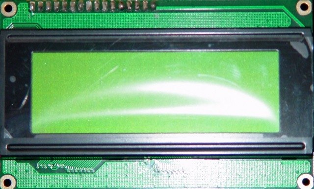
Driving a Hitachi 4x20 LCD
Trying to drive a Hitachi based LCD for the first time through a PIC or similar processor? Look no further!
The Hitachi LCD driver chipset is a standard in the world of micro electronics. While the datasheets are quite complete, they can be a bit of a pain to decipher if you’re not used to reading datasheets. Over the years, we’ve put together a number of electronic testing rigs for a variety of purposes and we’ve found the four line LCD display invaluable when it comes to quick and dirty output. How do you get your data onto the display?
There are three main things that we’d suggest you pay attention to. Number one, don’t forget to include some sort of rheostat for the LCD contrast control. You can save yourself a lot of pain and effort by installing one on pin 3 (Contrast Adjustment Vee) rather than trying to fiddle around wondering why you’re not seeing anything at all.
That out of the way, the other two main things to understand are that the LCD can operate in a couple of different modes. You can either operate it in a four bit mode or an eight bit mode. For simplicity, we’ve included driver code that will work seamlessly with a PIC16F819 and can easily be adapted for a large variety of other PIC processors with little to no effort. The code that we’ve included will expect to drive the display in eight bit mode, which is the easier way to go if you have the datalines to spare.
Other than choosing the width of the data that you will be sending, the two modes that you care most about are whether the display is in command mode or ready to accept and print a character. This is controlled by pin 4 on the display. Clearing this pin will set the display to expect a command. Setting this pin will set the display to expect character data to be output. In order for the display to operate properly, it’s generally a good idea to begin by waiting a few milliseconds after powerup so that things can settle down, then setting the data width and then clearing the display.
The last key to understand when using this type of device is the principle of “clocking” data. While we’re considering an eight bit bus in this example which makes the notion very easy to understand, it actually can be found in virtually all types of digital communications. Essentially, what we will do is set all of the pins that are used to represent the bits in the byte that we want to deliver to the display. In the code, this is done using the library function “output_b” which will put the appropriate values on the pins on port B of the PIC. These pins are driving the LCD data bus lines (pins 7 through 14 on the LCD module). Simply driving these pins high, though, is not enough to get the data into the LCD. Think about it, if the LCD responded to every voltage change on the data pins, we’d end up with all kinds of junk since the various bits will often not all change state simultaneously.
The way that we solve this problem is by using a sort of trigger to tell the LCD, “Ok, take of your blindfold and see what’s on your data pins.” That ‘trigger’ is also known as a clock signal. In fact, what we’re doing is ‘clocking’ the data, one byte at a time, to the display.
I stated earlier that clocking in this scenario is pretty easy to grasp. Where it requires a bit more thought is in situations where there are only one or two data lines available and we still need to get 8, 16, 32 or any other length data through that single line. The way we do this is by clocking the data one bit at a time. It is quite likely that the reason this confuses most people is that when they see “clock” they immediately think that they need to hook the system clock or crystal up to drive the input, but as you can imagine that could create all kinds of hassles! In more advanced applications, though, it can make a lot of sense to drive this bus clock through a divider that is driven directly by the system clock, removing the requirement for you to manage this clock “manually”. For another example of clocking data, take a look at the source code for the credit card reader. It has an example of how to clock data out of the buffer of the magnetic stripe reader head.
LCD Driver.c
LCD Driver.h